|
| HOME |
 |
The frame building
started by laying out a nice spot in the shop on a poured concrete slab
where the the machine would stand. A major step was to decide how to cut
all the 1/4 and 3/16" thick tubing, angle iron, flat bar and some other
profiles. I settled on a Milwaukee 8" metal cutting saw which proved
to be MUCH better a choice compared to an abrasive cutoff saw or any other
method of cutting. This carbide blade saw cuts steel dry like you would
cut hard wood with a circular saw and it cuts without burrs with smooth
milled ends and NO dust. The tubing ends were not even warm after the cut!
Tap Magic is a great lubricant for this and extends the blade life significantly.
The saw is a great machine for the money but it has a flimsy base for accurate
cutting which I had to compensate for by clamping a cutting "offset"
jig to the steel to guide the saw. All the cuts were first scribed using
precision squares and parallels and most of the cuts were within 0.25mm
with the more critical ones oversized and then ground down to the scribe
line with a beltsander/files and checked for squarness with a precision
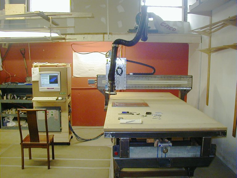
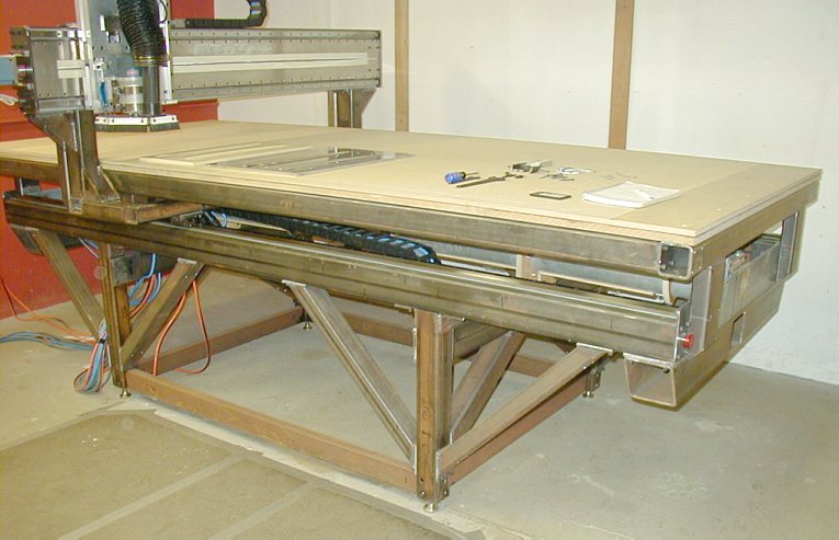
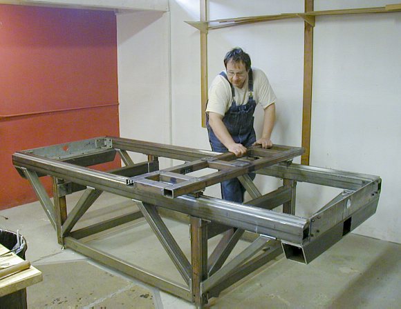
square. Then I clamped the precut beams, legs, crossbraces and flanges together section by section as square and accurate as possible, tig spot welding things together in "rough" alignment and then finishing the entire weld. Welding is excellent when you want strength and simplicity in joining of awkward pieces together but it is not good enough for precise alignment since the weld shrinks and warps the steel even with thoughtful pre-stitch welding (and a few of us have stress relieving oven for steel handy or a precision grinder for later). Also, plain structural steel is not rolled perfectly square and flat, so plain bolted steel to steel joints are not workable because the contact area is only about 15-20% if you are lucky and torquing things tight together is very bad since it leaves the steel in strained condition and the structure will keep twisting and creeping and you will never align the machine. It may not be visible by a naked eye but in the 0.01" scales and smaller the movement is very noticeable, not to mention the fact that by bolting together unground steel will NOT make an accurate machine. It is one thing to clamp a dial indicator to your machine and cycle it a few times to see that it comes back repeatably to some very small number BUT this test usually happens without any "deflecting" loads (a mill plowing through the material) and it says absolutely nothing about the relative alignment, straightness and "squareness" of the axis to each other. Despite all your effort invested in accuracy during construction, you never quite know how good this thing really is until you put it to task on some real work. This is a VERY long time of anticipation and the one thing you do not want to find out at the end of the road is that you produced an sloppy dud!! Repairs of this magnitude must be utterly demoralizing. I get queasy just thinking about it. So, here is the secret #1 to MadVac CNC accuracy. All metal to metal joints on the machine (with very few rare or non critical exceptions) are done by sandwiched, poured or injected metal powder loaded epoxy filler between the components in unstressed and aligned condition. Once thoroughly hardened, the sections were not separated until the joint is secured in alignment by reamed holes with tapered ground pins. The actual holes for machine screws (M8, M6 hex cap screws) that hold the sections together can be spot drilled, drilled through the "lower" sections using the top section as drill guide and then tapped, chamfered, holes enlarged etc (or the holes already exist)... This process results in having 95%+ contact between the bolted sections and the alignment stays well under the 0.0001" range since metalized epoxy shrinkage is in the 0.0001inches/inch range and very strong in compressive strength. I have used a mix of stainless steel powder (10lb $8 Ebay) in combination with powdered aluminum (to fill the interstitial space of the larger steel powder grain) and 207West System epoxy. If you want to know what I am talking about in more detail check out the Moglice web page. Needles to say, you pay for the accuracy with this really time consuming process of "epoxy joinery" which entails sanding and etching one surface to adhere to epoxy (hydrochloric acid/ Muriatic acid) and mold releasing the other surface with wax and silicone mold release (carnuba wax with Smooth-on all purpose mold release spray). On the more critical alignment joints, some sections were tapped with 10-32 threads and the fine adjustment/alignment between sections took place with 10-32 thumb screws to get the <0.0001" movement on the master precision level or dial indicator. Some sections were aligned, dammed with clear packing tape and the epoxy slurry was injected later into the joints with air escaping through pin holes punched in the corners of the "dam". You can see the epoxy filling the cavity and when the slurry reaches the pinhole, it is taped over and the injection stops. The pocket between the components is filled completely with metalized epoxy and there is no mess since the fluid is contained within the "dam". This is how all of the Y gantry was "fixed" plumb and square in every direction as well as the ball screw plumber blocks on X and Y axis. As you can imagine, this is some process but as far as I am concerned, this is the ONLY way to make an accurate steel machine without the help of precision milling or surface grinding machines to prepare and align the contact surfaces. Also, each member to member joint on the frame is fastened with a minimum of four M8 screws and two #2 x1" tapered pins. One side benefit is that the interruption of the joints with a material of different density helps in dampening the transmission of some vibration frequencies. The pictures in the left collumn show the still unfinished but functional machine. The frame is all steel made from square and rectangular tubing 3/16" and 1/4" thick. The total cost of the steel was right about $1000. The vertical legs of the machine are 3x3"x1/4" tubing, the X axis linear slides sit on 3x4x3/16" tubing. All diagonal bracing of the legs is 2x3x3/16" material. The table "ribs" are 1.5"x3"x1/8" with the main periferal frame of 3"x3"x1/4" stock. At the beginning I have seriously pondered extruded aluminium for the structure but aluminium is far more flexible (about 5 times the deflection of the same profile under the same load as steel) and about 10 times as expensive than this steel inch for inch. The table is suspended at the ends of the machine allowing the gantry to slide underneath in the full length of the ballscrew and the gantry clears the table on the sides by less than 1/4".Under the table you see the end of the ball screw showing through the hole and the aluminium plumber block which houses the ball screw and bearings right above the hole. The table surface is made from 3/4" and 1/2" MDF (~$200) glued together into 1.25" slab to create 3 interlocking sections for the whole table. I was considering phenolic sheets but it is way too much $$ for something that gets cut into. The thing about MDF is that it is dimensionally stable but subject to moisture absorbtion and expansion and contraction. In August, I would hear this thing popping and creeking which is not good, so I took it off and applied even epoxy coating over the whole sheet, holes and sides included. The epoxy soaks in and provides a very effective moisture barrier. Now the table is even more rigid and seems to dampen vibrations better and no creeking. The machinable area on top is made with epoxy putty applied with a notched trowel which is then machined (surfaced) flat. Now, any cutting below the surface of the table happens in the layer of epoxy, thus not disturbing the moisture barrier and restoration of the surface is cheap - fill grooves with more putty and machine flat once a year. The table is attached to the steel frames below in a grid of 30cm by M6 screws recessed 5/8" into the MDF. |
 |
I
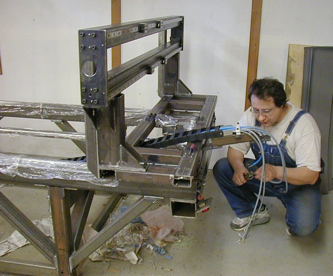
could have designed a less complex leg structure but I wanted a machine
that was easy to walk around without kicking into the legs and had a smaller
footprint for easier cleanup and for easy access to the ballscrew. This
diagonal truss structure runs in both x and y directions and is very rigid.
When you have a 300lb gantry zipping around at faster feed speeds you do
not want dynamic deflection of the members on sharp direction reversals
in the XY plane or binding of the linear slides as the frame tries to twist
into a parallelogram due to the inertia of the gantry. Also, emergency stopping
of the machine at full speed is a very drastic thing when you bring a 300lb
mass to an immediate stop! This kinetic energy has to be contained/absorbed
somehow and you want all the strength you can get in every part. The ends of the frame on which the ball screw plumber blocks are mounted are made from a 6x6x1/2" angle iron. I found these 2 zinc coated pieces as scrap for eight bucks. These members are bonded to the large 6x6x3/16" tubing underneath for torsional rigidity. The x axis ball screw has "fixed-fixed" ends and the axis of the screw should remain rigidly horizontal at their mountings. The weight of the ball screw however makes it sag about 3-4mm in the middle when the ends are free and if the mounting of the plumber blocks is on a flexible foundation the ball screw will tend to twist the plumber blocks down causing friction, strain on the ballscrew and binding when the gantry is at the very ends of its travel. Ballnuts do not like big side loads as they are designed for purely axial loading and I like to keep the screw/nut as unstressed as possible. On this machine the ballnut stops only 3/4" short of the plumber block by limit switches! The gantry is designed to collide with the end stops when the screw is just 1/2" from the bearings, thus protecting the expensive screw from tearing out its own ball bearings from the plumber block (and it would have no problem doing it). The frame sits on 4 all steel "swivel base feet' with a 1/2"-13 threaded stem and locking screw (ENCO). The final leveling is not much fun since the 1/2" thread is very coarse for fine height adjustment but it is possible to level the frame to 0.001". The machine sits on the thread but since there is a backlash in the tapped hole, the locking counter nut wants to lift the machine as it is tightened. It takes some play to get it leveled. The feet are also available with rubber pads which is tempting to use in terms of vibration dampening but precise leveling of the machine becomes nearly impossible. You want steel on concrete. |
 |
Testing the lower gantry for smoothness of motion. Very smooth, no binding
anywhere. I am pushing it at about 300in/min without problems but the resistance
of the grease-packed preloaded linear bearing becomes noticeable. I measured
the rolling friction on the gantry frame at about 13lb after the initial
"stick-slip". Straightness, accurate level and parallelism of the slides is of utmost importance if you like to have a happy machine and to keep your hair a little longer. The sliding gantry lower frame (show on left) is carefully TIG welded together into a solid frame and rides on 4 linear bearings that are about 15" apart on each rail. The ball screw runs in the middle of the rails. In this type of design one must be careful about "off center" loads (such as heavy metal milling which will not happen here) that would want to "retard" the slides on one rail and thus causing binding of the linear bearings. The smaller the spacing between the linear bearings on each rail, the greater the chances of this happening. Essentially the ratio of the width of the gantry to the spacing between the slides makes the system (any system of this type) "unstable" and with large enough off-center forces the gantry would either bind/ stall motors or push the rails apart. A stable system would have longer gantry than it is wide but it is not a practical arrangement. In this case, a rigid frame firmly mounted to preloaded bearings and good alignment lets you get away with this configuration. In order to avoid potential binding and to sustain heavy off center loads, gantries of this type are generally designed with rack and pinion where the pinions on each side are rigidly connected together or are run by synchronized motors. Some gantries also use two ballscrews each run by synchronized motors slaved togeter in the software. The theory behind these designs is that the gantry will not "cock" (one side getting ahead of the other) if there is a large off center resistance. Both sides will always move in concert. This is a nice theory but it is more difficult/troubleprone and expensive to implement as a "home made" system for many reasons and can be a real nightmare if the motors do not stay in sync (thus causing a more severe problem that it was designed to prevent in the first place). This puts a significant strain on the linear slides which doesn't go away until the motors are referenced by limit switches. Nowing what I know now about motors losing steps, stalling, line noise problems, tuning, the huge forces involved etc.., I would not do the double ballscrew design even if I got the second motor and screw for free. The only way I see this as an option is if the two sides were mechanically linked but that introduces backlash and additional problems. Here are the specs for the HIWIN rail and linear bearings used on the x and y axis. LGH25 CA 2R 2895 Z1 H + KK LGH20 CA 2R 1753 Z1 H + KK LG (type of block) H(square type)(25 width of rail)C(heavy load rating)A(mounting from top)2R(number of blocks per rail)2895(rail length in mm)Z1(light preload)H(high class precision)KK(double end seal + scraper + bottom seal). See the Hiwin catalog. |
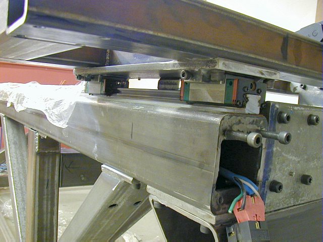 |
Looking at the X axis linear bearings and E-stop switch (and machine grounding
point) hanging out. The linear bearings are aligned and attached to the
3/8" x 4"x 16" steel plate above them. Here again the bearings
rest aligned on an epoxy cast "L" shaped cradle. Note the screw
on the side which pushes the bearing against one leg of the "L"
(a block welded on the plate embedded in epoxy forms the stop). This arrangement
is important to stiffen the gantry against cocking and assures squarenes
of the gantry relative to the slides at all times. The cast L profile was
molded using the largest "square" as the mold (shown below). The x axis rails are mounted on a "hand scraped" 3mm epoxy bed using the same principle of "scraping" as is done on cast iron sliding surfaces of heavy machinery. See the interesting Moglice literature on this subject. This was a very interesting experiment in making perfectly flat and level surface on both sides (lots of smudging with Prussian blue and high spotting with the ground straight edge and the large ground square). You would think that ground linear rails are naturally straight when they arrive at your door but these things are like steel spaghetti and you have to mount them to a perfectly flat surface and also make them run straight. In industrial machinery this is arranged by a precision ground groove machined into the steel or cast iron bed on which the rail is then mounted. Here the straightness of the master rail was set with a 0.009"dia. steel guitar wire (MasterCarr) tensioned heavily next to the top (master) edge of the rail and then the gap between the two adjusted using a microscope like loupe from binoculars. This was based on the assumption that such a light and strong wire will be nicely straight under high tension and with negligible sag. You can now guess how the epoxy beds under the rails were cast and scraped using the wire as a reference plane. The wires were leveled, tensioned and then encased in the epoxy pour. The epoxy was then scraped carefully to the top of the wires on both sides. When you get close to the wire tops, the Prussian blue smudges allow much more precise local scraping and wet sanding with 400 grit paper backed by a granite block. Anyway, the 0.001" space between the wire and the rail looks like a thick line on a ruler under the loupe so the rails are pretty much straight to a deviation of about +-0.001" along the whole length of the rail. This is very good for home made setup and it shows in the smoothness of the gantry. The rails are "locally" straight without humps but you can deflect them over 3" easily "globally" along the whole length. The main concern therefore was "global" alignment and the wire method is a bit tedious but it is the best thing I could come up with short of laser alignment. There is NO other visual method or a mechanical straight edge that will deviate less than 0.001" per 115" length. The drilling/tapping of the linear rail screw holes was also a lot of fun (M6 threads). The holes on the X rail are spaced about 60mm and the rail is 289cm long so there were about 48 holes to be drilled and tapped - exactly. First, the rail is clamped in place, aligned roughly (+/-0.005")with the wire, more clamps are added, a drill ground to slip in the rail holes was made and used to spot drill all the holes into bare metal through he epoxy bed (center punch was not accurate or deep enough). Then, the rail is removed and 5mm holes are drilled, chamfered, and tapped. You have to be absolutely focused on the drilling and tapping to make sure the holes are positioned correctly and perpendicular! It is easy to drill 0.5mm off center but that is about the space between the screw head and the hole in the rail. Anything more and the screw will not fit in the rail together with its 48 neighboors not to mention that you cannot move the rail for alignment afterwards (and you cannot weld over the hole to start over since the epoxy bed will melt). The last chance is to grind down the diameter of the screw head. Be sure to debur the mounting bed and the linear rail and to degrease the contact surfaces. Before degreasing, my last cleaning operation consisted of lapping the epoxy bed with a few passes of 1000grit wet dry paper on a granite block. I would estimate that the entire machine required a few thousand drilling, chamfering and tapping operations. |
|
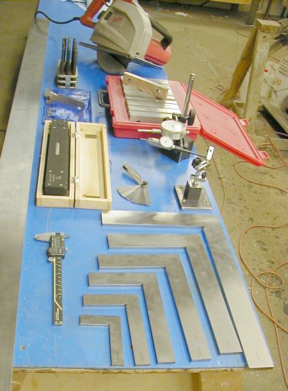
My
most important tools of the trade. A complete "must have" for
a project like this. Starting form the left. 1) 6 foot long ground steel straight edge - McMasterCarr 2) center punch set, adjustable parallels, master precision level 3)calipers, ground squares, thickness gauge, set of 1/2x6" parallels 4)dial indicators - the smaller one (with 0.0005" per division 0.03" travel) is vital.The large one 0.001" division and 1" travel. 5)Milwaukee metal cutting saw Everything except the straight edge and the saw is from ENCO. The master level, the squares and the parallels are Polish made and of top notch quality hardened steel. All this and much more is counted as part of the cost of the project. (~$900) |
|
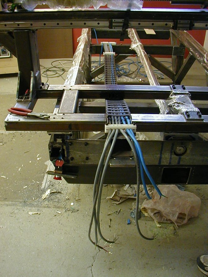
Wiring
for the whole y and z/w axis run through this 1" x 3.5"x 6ft Gortrack
energy chain (McMaster). This is a fun stage in the project when you start
seeing results. The wires are run through the metal tubing wherever possible
to be out of the way. Wiring: all stepper wires are connected with 4 conductor 18awg shielded (SAB CC 600) automation cabling. All 8 limit switches on this machine are hooked into ONE shielded 8 conductor 22awg cable with twisted pairs. Each pair of twisted wires takes care of one axis. In order to do this of course, I had to cut into the cable from the side in places to wire in the switch. Be sure to ground the machine to the controller and use only shielded cables also grounded ALL at the same SINGLE spot on the controller (star grounding configuration). These two things go a long way in minimizing the risk of electrical noise on the wires (and missed steps, roughness etc...). This is very cheap and effective preventitive step. Ignore the trash under the machine. No one wants to clean up in the heat of machine building and the screws and rails are always protected from dust with kitchen plastic wrap. My philosophy is to devote 110% to the things that "count" in the functionality of the machine. Things like aesthetics and neatness assume the last place, there is already enough stuff to spend your time on. |
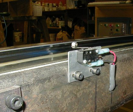 |
Here
is the x limit switch ($2.50 item from MPJA).
All limit switches on the machine are the same. If careful and slow, you
can get homing/referencing repeatability of 0.002" on the switch. There
are even smaller microswitches like these that can get down to 0.0003".
The trade off between mechanical limit switches like these and optical or
inductive electronic switches is accuracy, cost and wiring. These switches
just need two wires and you can wire them in series so 2 switches run on
one pair of wires (signal and ground from the breakout board). This is why
you can run 8 limit switches on 4 pairs of wires in a single cable. Electronic
switches on the other hand need 3 wires for each switch (output signal,
supply voltage and ground). This simple micro switch has 3 contacts. Normally open (NO), normally closed (NC) and common. In this case the wires go to the NC and COM terminals which leaves the switch closed and current flows through the switch while the machine runs (active high). When the gantry hits the switch, the circuit opens, indicating to the breakout board/Mach2 that the switch has been tripped and the machine stops. This "normally closed" wiring is vital to the health of the machine (and you). If any wiring is broken/disconnected or the switch is bad, the system will not let you reset until you fix the problem. Conversely, if you run on a "normally open" circuit, nobody will know that a wire may be broken or unplugged until the ballscrew rips off the end of your machine - $urprise!! |
|
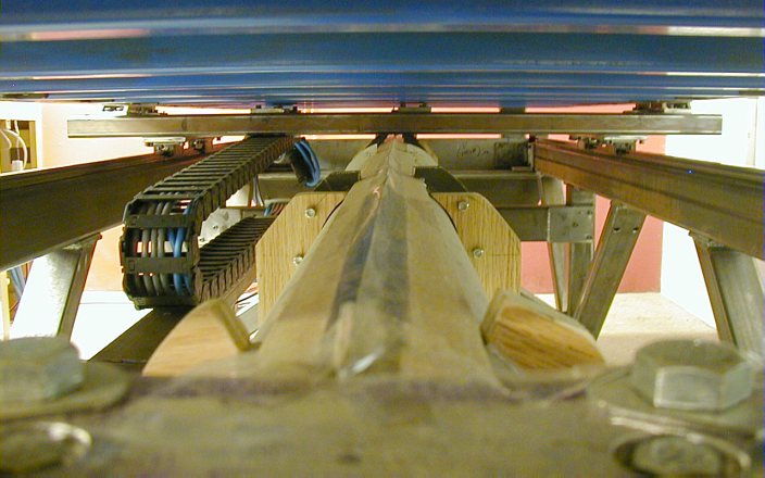
Clearance between the ballscrew and the lower gantry. You want to get everything
as short and compact as you possibly can. Longer overhangs have more inertia
and will impose larger dynamic forces / amplitude of lower frequency vibration
on the machine during reversals and accelerations, deceleration and sudden
stops. See the locking nut on the ballscrew? This is a M35x1 metric thread and nobody had this thing except Maryland Metrics (as well as the spring washer behind it). The ball screws come without anything; just the screw and the nut on it. Commercial plumber blocks for much smaller screws go for about $250+ each. If I could even find something to fit this screw, I would guess the cost per plumber block would be around $1000? My cost was ~ $100 for all the materials for all blocks ( 6061-T3 aluminum block 3"x 13"x 10", epoxy, screws) + time. |
|
 |
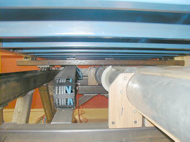
Looking
down the 9.5 foot ballscrew protective housing and energy chain to the left
of it. Table above. If you are going to blow a few grand on a mechanical miracle like a ground ball screw and your shop happens to be like a Sahara desert of metallic and carbide abrasive dust, you must have one of these. This design allows full length travel of the ball screw with the ball nut being connected to the gantry with a vertical steel plate that rides in the top slot of the housing. The lubricated plastic seals close over the slot as the gantry passes by (see them closed at top). The housing is a bunch of galvanized 5" diameter pipes from Home Depot split lengthwise/stiffened epoxied together and mounted in two places on the two crossbraces of the frame. There is no other contact between the housing and the machine other than clear tape seals to the plumber blocks at the ends and the top slot seals. Why not rubber or plastic bellows? Because for every foot of full extension they use up at least 10-30% of that length in the compressed state which would rob this machine of significant useful travel. Besides, this was a much cheaper / maintainable solution (opens like a clam shell) and works perfectly, and it was one of the finer inspirations since I have not seen this particular implementation yet.. The flange of the ballnut has about 3/8" of concentric clearance on the inside of the housing. It is important to plan for all this and how to mount it ahead of time. |
 |
One of the dust housing mounts. Plywood was good enough. The tension on the cables must also be adjusted so that they do not cross each other in the Gortrack chain. |
© Copyright
Vaclav Stejskal
All rights reserved
Last page update:
11 May 2005